|
Republic
RC-3 Seabee Specifications
|
|
Home | RC-1 |
RC-3
|
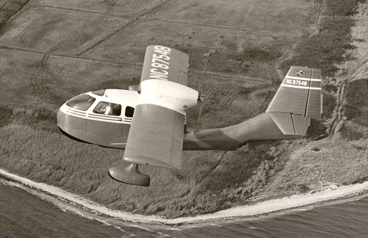
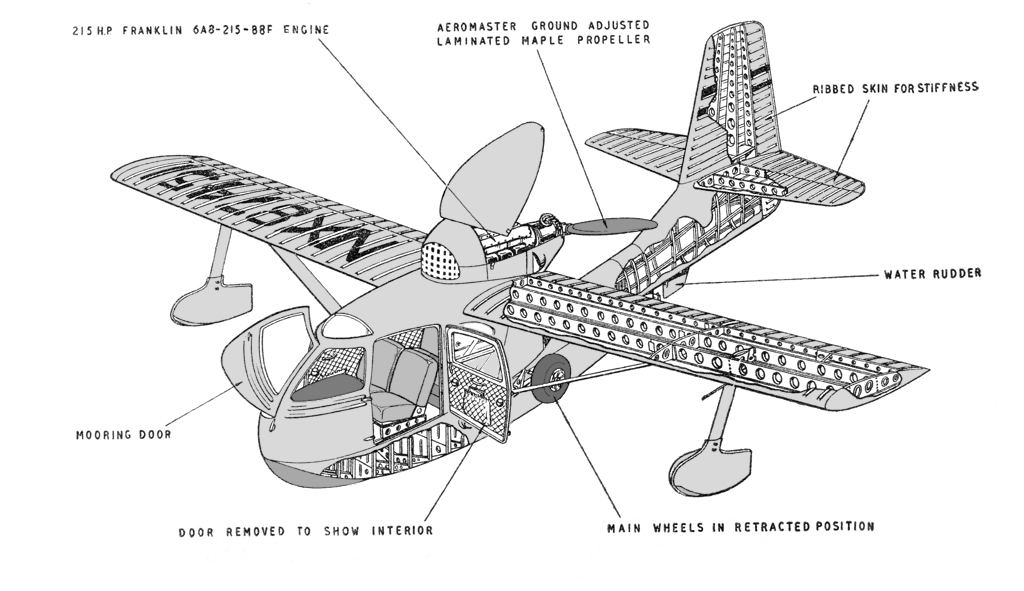
Republic RC-3 Seabee
Photo: © Republic Aviation Corp.
|
Seabee
Design Philosophy |

|
As a prelude to the structural analysis of the Seabee, it is interesting
to outline the considerations leading to, and the theory
underlying, the simplified design.
The prototype Republic RC-1 Thunderbolt Amphibian (NX41816), which was completed in
November 1944, was built only to
prove the general design. The aircraft was a three-place 175 hp all-metal
amphibian monoplane using conventional structure throughout,
and was an outgrowth of the original S-12 Air Car amphibian design by Percival
H. Spencer, who became a development engineer with RAC.
Manufacturing cost considerations - price would have had to be almost
twice the initial price (just under $4,000) based on simplified design -
prompted RAC president Alfred Marchev to direct an
investigation to determine how airframe structures could be simplified
to reduce manufacturing costs sharply. He believed that extensive
simplification could be achieved, with consequent great reduction in
number of assembly components, while yet maintaining the high standards
required in aircraft construction.
 Alfred Z. Boyajian, structures project engineer at Republic, was
assigned the task to redesign the Seabee airframe to meet reduced cost
requirements. As a preliminary step, he reviewed: (1) The
evolution of conventional design, to ascertain why this type of
structure had been adopted; (2) production time studies, made available
from wartime experience, to establish what, in general, was causing
manufacturing costs to be so high and (3) stress analysis procedures, to
determine what conceptions existed which might be altered to justify a
vastly simplified structure.
Alfred Z. Boyajian, structures project engineer at Republic, was
assigned the task to redesign the Seabee airframe to meet reduced cost
requirements. As a preliminary step, he reviewed: (1) The
evolution of conventional design, to ascertain why this type of
structure had been adopted; (2) production time studies, made available
from wartime experience, to establish what, in general, was causing
manufacturing costs to be so high and (3) stress analysis procedures, to
determine what conceptions existed which might be altered to justify a
vastly simplified structure.
It became apparent that: (1) Despite the progression from the wood and
fabric covered wing to the all-metal unit, the latter was still
fundamentally similar, in basic pattern, to the former; (2) production
complications arose because of the complex "egg box" structure
- many internal interconnected members, in turn connected to the
outside cover; and (3) the necessity for the retention of numerous rib
components (as "irreplaceable" internal members of the
conventional metal wing) had not been clearly established.
When engineer Boyajian's simplified - comparatively ribless - structural
design was first proposed on paper it was subjected to much discussion
in large conferences of engineering personnel. The absence of
conventional ribs in the design created much doubt as to structural
airworthiness - doubt voiced because it was believed that in accordance
with customary methods of stress analysis, the proposed simplified
structure was considered to be probably deficient in strength
requirements. It was considered, generally, that other than a rib there
was no structural member deemed capable of transferring airload shears
in a chordwise direction to the bending resistant spars.
Boyajian's theory was that if the cover of a stressed skin wing were
sufficiently stiffened, thus creating a heavy torque box, it should be
possible to transfer such airload shears with a minimum of internal
structure. He arrived at this conclusion after reasoning that the
conventional practice for' a stressed skin wing, wherein a section is
isolated and analyzed as an independent structure, was not justified,
since it was assumed that the other portions of the overall structure
did not contribute any vital additional strength characteristics to the
isolated section.
True, an isolated ribless section would deflect under airload, because
of absence of shear rigidity, and would give a large torsional
displacement with respect to the end ribs. But a torque box, for
example, comprising the stressed skin leading edge would offer
appreciable restraint to such torsional displacement. Further, Boyajian
believed that the leading edge cell and the aft cells would serve, in
some degree, as beams in bending between end ribs, and that the
secondary spars would also act so; He also reasoned that individual
beads on leading edge skin would serve partially as truss members pinned
at the leading edge.
In effect, Boyajian's proposal was a new application of the theory of
stress analysis - a radical departure from conventional practice - which had
to be substantiated by static test as the design proceeded, since the
stress in the simplified structure could not be adequately calculated.
In the face of doubt and disagreement, but encouraged by Mr. Marchev,
the simplified design took shape unit-by-unit, as hand-built specimens,
for test purposes.
As an initial step in the development program, the conventional
prototype stabilizer -a fair example of a costly all-metal structure
consisting of spars, ribs, and stringers - was selected for experimental
simplification. Aim was to effect radical manufacturing cost reduction
without sacrificing strength-weight characteristics and serviceability.
|
Below is a comparison table between the conventional
prototype construction and the simplified production construction:
|
|
Group
|
Construction
|
Parts
|
Manhours
|
Rivets
|
Weight
|
|
Stabilizer
|
Conventional
|
42
|
14.2
|
521
|
13 lbs
|
|
Simplified
|
9
|
2.7
|
160
|
13 lbs
|
|
Wing
|
Conventional
|
114
|
280
|
2627
|
150 lbs
|
|
Simplified
|
30
|
10
|
882
|
110 lbs
|
|
Hull
|
Conventional
|
362
|
590
|
6500
|
318 lbs
|
|
Simplified
|
63
|
20
|
2400
|
298 lbs
|
|
Technical Description |
|
Landing Gear
|
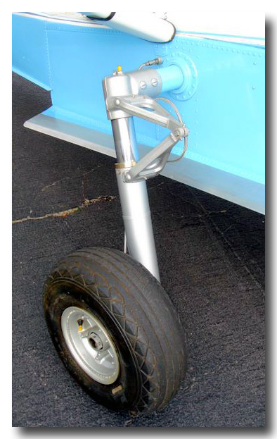 The landing gear on the Republic Seabee - an Electrol product designed
especially for use on medium and lightweight personal planes - is a
straight leg, hydraulic, full cantilever design which can be use on
fixed or retractable undercarriages. The piston does not touch the
side of the cylinder because of two bronze bearings located in the lower
half of the cylinder. Elimination of all sliding motion against
the interior wall of the cylinder contributes to the efficiency of the
unit as well as to economy in its manufacture. Because of the lack
of relative motion between the bearings and the cylinder wall, the
cylinder needs only to broached and not honed in the manufacturing
process. In fact, one of the features of the Electrol design is
that all work on components is confined to machine operations on either
one side or the other of the element, but never on both.
The landing gear on the Republic Seabee - an Electrol product designed
especially for use on medium and lightweight personal planes - is a
straight leg, hydraulic, full cantilever design which can be use on
fixed or retractable undercarriages. The piston does not touch the
side of the cylinder because of two bronze bearings located in the lower
half of the cylinder. Elimination of all sliding motion against
the interior wall of the cylinder contributes to the efficiency of the
unit as well as to economy in its manufacture. Because of the lack
of relative motion between the bearings and the cylinder wall, the
cylinder needs only to broached and not honed in the manufacturing
process. In fact, one of the features of the Electrol design is
that all work on components is confined to machine operations on either
one side or the other of the element, but never on both.
Adapted as standard equipment on the Republic Seabee, this gear has
attracted considerable attention as it becomes a main component of an
aggressive simplification program. Claimed for it are ruggedness,
light weight, simplicity and interchangeability of parts. Quick
and accurate assembly is another asset. An entire oleo assembly
may be disassembled in one and one-half minutes.
Special attention was paid to reduction of the number of units in
each assembly, ease of maintenance and a reduction in unit costs.
The volume of air entrapped in the oleo has been held to a
minimum. A small amount of air is desirable to avoid rebound while
the aircraft is being taxied.
The reliable, hydraulically controlled landing gear is maintained in the up or
down position by the geometry of the linkage. As noted on the landing gear
diagram, the linkage is designed so as to “break” during the transition
phase of the gear operation and to “remake” at the up or down position, so
that the center pivots of the linkage are past dead center travel. In this
manner, positive lock is maintained until hydraulic pressure is applied to the
cylinder permitting a “break” in the linkage.
Note that the tail wheel is rotated (to starboard) to the up and down position and that the main gear is retracted and extended. The landing gear position lights (Red and Green) are wired so that when all three wheels are down and locked the green light is illuminated. However, when the Red light
(UP) is illuminated it does not necessarily
mean the tail wheel is locked up. It may be down or any position including up and
locked. Use the wing float mirrors to confirm the tailwheel position.
Main landing gear utilizes Electrol air-oil struts designed to have a
relatively low static air pressure to facilitate servicing. Each strut is fully
cantilevered from the hull side and through a bolted elbow connects with a shaft
extending through the hull to the opposite gear. Bull shaft is in two sections joined at
the hull centerline by a welded sleeve. Channel members at each end of the sleeve
provide support by extending to the frame at the hull bottom.
Strut torque arms (scissors) are utilized as step means to the cabin,
and top torque arm is designed to receive a towing hook.
 Retraction and lowering of the main landing gear (equipped with Goodrich
wheels and brakes) is accomplished by hydraulic power from an Electrol hand pump
located between cabin front seats. Reservoir, thermal expansion valve, and selector
valve (flaps are also operated hydraulically) are integral with the hand pump. A
bellcrank on the center sleeve connecting the two sections of the hull shaft attaches to
the upper arm of a two-arm toggle linkage; lower arm of linkage is attached to a
pivot fitting on the hull structure and above this pivot point is also connected the
piston of the hydraulic cylinder. Latter is in turn pivoted on a horn attached to
the center sleeve. Extension of the piston breaks the toggle linkage from a
past-dead-center positive-lock position and rotates the hull shaft to retract the gear.
At full-up position of the gear, the linkage again comes together just past dead
center to form a positive lock through contact of positioning stops at the break
point.
Retraction and lowering of the main landing gear (equipped with Goodrich
wheels and brakes) is accomplished by hydraulic power from an Electrol hand pump
located between cabin front seats. Reservoir, thermal expansion valve, and selector
valve (flaps are also operated hydraulically) are integral with the hand pump. A
bellcrank on the center sleeve connecting the two sections of the hull shaft attaches to
the upper arm of a two-arm toggle linkage; lower arm of linkage is attached to a
pivot fitting on the hull structure and above this pivot point is also connected the
piston of the hydraulic cylinder. Latter is in turn pivoted on a horn attached to
the center sleeve. Extension of the piston breaks the toggle linkage from a
past-dead-center positive-lock position and rotates the hull shaft to retract the gear.
At full-up position of the gear, the linkage again comes together just past dead
center to form a positive lock through contact of positioning stops at the break
point.
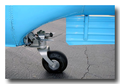
Tail wheel is full swiveling and is looked in the fore-and-aft position
by a spring-loaded pin with cable connection to cockpit. The wheel is
mechanically raised via a cable connection to the main gear hull shaft. Cable action
pulls a lock-pin and then rotates a horizontal shaft on which is pivoted the
largely by automatic riveting process. Crown skin is an .040 beaded pressing
attached to
the crown bow member with the same rivets which fasten the side skins.
|
Fuel System
|
The fuel system is as simple as it gets. Fuel for the Seabee is contained in one bladder type cell of 75 U.S. gallons capacity located in the hull under the aft baggage compartment. The fuel is piped to the carburetor through a strainer and pumped by two AC diaphragm type engine driven pumps. Either pump can supply sufficient fuel to the engine. Some of the later model Seabees have an electric pump, in addition to an engine driven pump, located close to the fuel tank to provide fuel under pressure to the carburetor.
The fuel quantity gage is electrically operated from a float in the fuel tank. A fuel pressure gage indicates pressure for either the left or right fuel pump (or the electric or engine driven pump) as selected by a fuel pump switch on the instrument panel.
Normally the fuel is shut off by pulling the mixture control to the idle cut-off position; in emergencies fuel may be stopped by pulling on the fuel-flow shut-off control located under the pilot’s seat.
Before the fuel gets to the pumps, it is filtered. This filter should be checked on each pre-flight check and is normally located under the right wing root but some have been located on the other side. Boost pumps and fuel system components may vary from Seabee to Seabee. Check your FAA Approved Flight Manual and STCs for your specific components.
|
Flight Controls
|
The control surfaces of the Seabee are actuated by the rudder pedals and the control wheel through a series of flexible cables housed under the cabin floor and lead through a series of pulleys to the control surfaces. The dual rudder pedals are synchronized with the pilot’s pedals by mating gears on the connecting torque tubes between the two sets of pedals and the dual control wheel is synchronized with the pilot’s wheel by engaging a split sprocket in the dual control column to a mating sprocket in the pilot’s control wheel column. The dual column is removable and may be stowed under the front seat in the bracket provided.
The water rudder cables are spliced to the air rudder cables so that operation of both surfaces is synchronized and made by the same pedals.
Some models of Seabee have steerable tail wheels that are also part of the rudder cable assembly. The rudder pedals also control the tail wheel steering system.
The elevator trim tabs are controlled through sprockets and chains at the control and the surfaces. The control is by crank located overhead of the pilot. Fixed tabs are provided on the aileron and rudder. An FAA Airworthiness Directive has been issued for the elevator trim system. Each pre-flight should include a thorough check of the trim tabs on the elevators. No more than
⅛” inch play should be evident. If it is more than that, get a mechanic to check it. Steel bushings will negate the AD but it should still be checked prior to flight.
|
Hydraulic System
|
The flaps, main landing gear and the tail wheel are extended and retracted hydraulically. A single, manually-operated hydraulic pressure system activates both the landing gear and the flaps.
A large lever, extending upward from beneath the floor between the two front seats activates the pump with which hydraulic pressure is built up. Two other arms extending from this unit control the action of the fluid. The right lever directs the section of the landing gear while the one located on the left side determines the position of the flaps. The hydraulic power pack incorporates a series of check valves which prevent the temporary dropping off of pressure when transferring the hydraulic action from wheels to flaps or reverse. Some Seabees have an additional electric hydraulic pump operated by a switch on the forward instrument panel or control wheel button. Momentarily
activating the switch or button turns on the pump and pressurizes the system and
operates the selected flap or landing gear system until it reaches the up or down position and turns off automatically when the pressure in the system reaches a
predetermined value (≈800 psi).
The system has a three and one-half pint capacity and uses a petroleum oil base hydraulic fluid, Specification 3580D or equivalent (Mil-5606).
|
Brakes and Wheels
|
The main wheels of the Seabee are 7.00 x 8 and the tail wheel is a 10” smooth contour type.
Each main wheel is equipped with bladder-type brake which is fed from its own master brake cylinder at each of the rudder pedals. A brake adjuster and a parking valve are installed in each of the lines between the master brake cylinder and the wheel. The positions of these parking valves are controlled at the instrument panel by a single parking control lever.
A control is provided in the cockpit to engage or disengage a tail wheel lock thus permitting the tail wheel to be locked in the centered position or to be unlocked in order to swivel.
A steerable tail wheel assembly is available on some Seabees. These models use cables attached to the rudder cables that steer the tail wheel up to a certain limit. If forced beyond this limit, the tail wheel unlocks and is free to swivel until forward, straight movement locks it in the steerable position again.
Later modifications have been applied to Seabees that allow for an improved model disc brake system. These are typical disc brakes that are identical to the above system with the exception of the bladder and drum that are replaced by the caliper and disc. There is no adjuster in the system for they are self-adjusting.
|
Wing Structure
|
Conventional prototype RC-1 wing was a good, typical airfoil structure of
24ST -a tapered, full cantilever unit consisting of ribs, spars, and stringers. Here,
again, there were so many interlocking components, all largely inaccessible to
automatic machinery, that in the main it had to be assembled almost entirely by hand; hence,
it was very costly. Manufacturing of the many detail components was comparatively
simple, representing only about 5% of total wing fabrication time; the other 95%
was almost all assembly time.
The simplified wing on the RC-3 is a rectangular planform constant-thickness
structure, externally braced by a single strut. Reasons underlying the change from tapered to
rectangular planform were as follows:
(1) Skin becomes a rectangular sheet, and in bending it to the form of
the wing, material losses ordinarily occasioned with a tapered wing are avoided.
(2) A single forming tool can be used for all skin sections on both left
& right wing panels, whereas on a tapered wing, each skin section
requires a separate forming tool, and a different set of tools is required for the opposite
wing.
(3) A single tool can be used for fabricating spars in left & right
panels.
(4) Exact width strip-stock can be used for the spars, since the flat
pattern inboard end of the spar to make attachment to the cabin structure.
Attachment
for brace strut is accomplished with another forging at the center rib.
Middle spar - essentially a false spar - is an .032 channel member
fabricated in a manner similar to the front spar, but has no angle attachments.
Rear spar is a simple .051 channel member having a forging at the
inboard end for attachment to the cabin structure.
Between front and middle spars, at about one-quarter the distance from
the middle to the tip, is the wing float supporting structure consisting of two
pressings forming a socket for the float strut.
All spars are of R-301W material. Lightening holes have simple 45° flanges
formed without subsequent heat treating. Because of severe forming, ribs
are fabricated of 24SO, and are subsequently heat treated. Rib lightening
holes have deep drawn flanges.
Wing skin, with beading similar to that on the stabilizer, is R-301W
-.032 on inboard half and .025 on outboard half. Skin sections are pressed on a camel-back
draw die, similar to the method used for the stabilizer skin.
In assembly of the wing, skin sections are first spliced on an automatic
riveting machine to form a large envelope. Spars are installed progressively,
beginning with the front spar, and riveting is done on an automatic riveter afforded
access to interior of envelope from rear opening. Rivets are driven through both
upper and lower skins and through spar flanges at same time, in about 8 min. Wing
tip is quickly installed on outboard rib with sheet metal screws and self-locking sheet
metal nuts.
External wing brace strut is a single piece of .091 R-301W turned on
itself to provide a streamlined section joined at the trailing edge, on an
automatic riveter, along outwardly turned flanges. Extruded fittings on each end of the
brace strut carry one bolt for attachment to wing and hull, respectively.
Wing floats are R-301W .051 skins formed in a novel manner. Each float
is of fully
monocoque construction consisting of left & right pressings (clamshells)
joined at the plane of symmetry along outwardly turned flanges adaptable for external
automatic riveting. The strut connecting the float to the wing slips into a neck
section provided in the pressings. Complete float assembly consists of but five
parts - two skin sections, two bearing plates for strut bolts, and a drain
plug - and
can be fabricated in 15 min. This is in sharp contrast to conventional wing
floats with numerous bulkheads which are fastened to the skin by reaching through
access holes and driving each rivet by hand.
In this simplified wing design, notable lightness is achieved. Complete
with flaps, ailerons, brace strata, and miscellaneous fittings, it weighs but
1.45 lbs per sq ft - unusual, considering that the average wing loading is 16
lbs
per sq ft.
In static test, the wing sustained a load of 115%, and in torsional
rigidity was four
times greater than CAA requirements. Another unusual characteristic of
the wing structure was that no skin ripples or buckles appeared up to 100% of
design load - a condition rarely achieved in a conventional metal wing structure.
These very satisfactory results obtained with the large wing structure
justified the application of this theory of the unit is rectangular. This avoids
material losses and additional operations required for the tapered spar.
(5) Rectangular planform wing permits flaps and ailerons, and their
hinges and brackets, to be interchangeable left & right, thus eliminating the need for
separate tools and material losses attendant with the tapered design.
All of these considerations are extremely important in a simplified
structure. In contrast, small differences between two assemblies of a conventional
design (such as non-interchangeability
of left & right skin sections) were not of much consequence, since this
condition required only a new set of parts and tools-representing but a negligible
portion
of total manufacturing costs which were, largely, consumed in assembly handwork.
However, in the simplified design - in which handwork has been greatly
eliminated - small differences which require additional tools and prevent the use of
components interchangeably, add considerably to the cost of the structure.
Simplified wing framework consists of 3 ribs and 3 spars. Ribs are approximately
8-1/2 ft on centers and spars are approximately 15 in on centers.
Inboard rib is a 2-piece member-nose rib and after-portion. Center rib is made up of 3
pieces intercostal between spars. Outboard rib is a single member providing for
the attachment of wing tip by incorporating a wide flange.
Front spar, supplying about 90% of wing bending strength, is an .064
channel constant throughout the span and having straight flanges turned on a bending
brake. Extruded angles of 14ST are nested in top and bottom flanges and extend from
inboard end approximately three-quarters of the span towards the tip. A simple
forging is used on the
|
Movable Surfaces
|
Except for size and shape, the full-slotted flaps, ailerons, elevators,
and rudder are fundamentally identical in construction. Each consists of a single
beaded skin folded upon itself and joined at the trailing edge, and each has a
single stamped channel spar member near the leading edge.
Flaps and ailerons have round-nose end ribs with outwardly turned
flanges to afford easy access for automatic riveting.
Elevator has only one rib - inboard end - bolted to the operating torque
tube extending between left and right units. No outboard end rib is employed
because the tip is formed from the skin as a continuation of the trailing edge. The
latter is cut out for a flat stock trim tab at the inboard end, the tab being
attached by piano hinge.
Upper and lower tips on rudder are fabricated similar to elevator tip,
hence obviating need for end ribs.
On the flap there are three 1/8-in flat stock hinge fittings. Two are
mounted on the end ribs, and the third fitting, which includes an operating
horn, is mounted on a center nose rib.
On the aileron there are two 1/8-in flat stock hinge fittings and a
separate horn, which are attached to intermediate nose ribs.
On the rudder and elevator, the spar supports T-shaped extruded hinge
fittings.
Since the cross-section of the aileron is identical to that of the flap,
it is possible to use the flap-forming tools to fabricate the aileron skin, spar, and
ribs.
Flap, aileron, elevator, and horizontal stabilizer units are
interchangeable - with respective opposite - hand installations. Approximate dimensions are:
Flap, 9-1/2 ft long by 16 in by 4 in deep at spar; aileron, 7 ft long by 16
in
by 4 in at the spar; elevator (tapered in planform), 6 ft long by 20 in at
maximum chord, tapering to 10 in at tip, by 3 in average depth at spar; and rudder
(double tapered in planform) 8-1/2 ft long by 18 in at maximum chord by 4
in average
thickness at spar.
Replacement prices for the various complete assemblies, including attachment mechanisms, are expected to be under these figures: Flap $35;
aileron $50; elevator $25; and rudder $25.
Control system is conventional cable installation. Cockpit control is
standard wheel arrangement with provision for utilizing removable duplicate wheel for
co-pilot, who has rudder pedals but no brake pedals.
|
Hull Structure
|
The hull, designed so as to permit a major portion of riveting to be
done on automatic machinery, consists of three separate assemblies;
forebody, afterbody,
and stern. Assembled, it has six watertight compartments - 3 in the forebody, 2 in the
afterbody, the stern being the last compartment.
Forebody is comprised of four subassembly units; deck (cabin floor), two
sides and bottom. Deck is made in three sections - forward,
middle and aft.
Forward section is a single .051 24SO pressing, subsequently heat treated, and
reinforced with 3 hat-sections (12 transverse, 1 longitudinal) supporting cockpit flight
controls. Edge of this section has an upwardly turned flange for assembly to the
sides by riveting.
Deck middle section is .025 R-301W stiffened by four longitudinal hat-sections
supporting the front seats and landing gear brace channels. Margins of
middle section are also upwardly flanged for attachment to sides and to front
deck section. Attachment to rear deck is by a lap joint. Between the middle section
and the sides is a: 1/8 in R-301W Z-section longeron which becomes a simple angle
where it overlaps (for about 10 in) the front and aft sections of the deck.
Deck aft section is a single .051 24SO beaded pressing, subsequently
heat treated, and having upwardly turned flanges on the sides. At the rear, the aft
section of the deck overlaps the forward skin of the afterbody and also the step
bulkhead. A cutout is provided in the aft deck section for access to the fuel
cell (located between middle and aft bulkheads).
First two watertight bulkheads - .040 24SO beaded pressings, beat
treated are sandwiched between the flange junetions of the deck skins.
Sides of forebody are .064 R-301W made up in three sections flanged
outwardly at the chine, where it joins the bottom subassembly flange.
At the bow, forward of the front bulkhead, the bottom consists of left
& right .072 61SW skins (made in a draw die). From the forward bulkhead to the
step, the .051 R-301W skin (made on a bending brake) is reinforced by 7-hat
section transverse stiffeners having greatest depth of about 4 in at the
keel. On the
underside of the chine is an external reinforcing angle extending from the forward
bulkhead to the step.
The keel - a T-shaped 14ST extrusion provided with drain plugs for each
watertight compartment - runs aft of the first step for splicing to the keel of the
afterbody.
Various simple structures within the forebody serve to support the
battery, hydraulic pump, and landing gear mechanism, and also provide anchorage
for safety belts.
Afterbody - hull section between steps - is comprised of an upper section
and the bottom as subassembly units. Upper section is fabricated from three
pieces of .051 R-301W, each developable from a flat pattern, joined by
simple lap
joints. Rivets through the lap joint between first and second skins pick up
the flange of the forward watertight beaded bulkhead.
Afterbody bottom is a single sheet of .051 R-301W (formed on a bending
brake) reinforced by four hat-sections, as in the forebody.
An indication of the sturdiness of the bull bottom structure is that
after more than 600 water landings, no dishing or skin ripples were observed.
The bulkhead at the second step supports the tailwheel and is formed
as an .040 24SO beaded pressing, subsequently heat treated. At the lower portion of
the bulkhead is a bearing plate reinforcement for attachment of the
tailwheel.
Flanges of the bulkhead face forward and are sufficiently wide to provide a foundation for a
butt joint between afterbody rear skin and stern skin. The splice is further reinforced at the bottom by an .051 R-301W
structural fairing.
The stern consists of two subassemblies - left & right halves - comprising a clamshell skin structure of .040 R-301W with a cutout at the rear top portion
beneath the fin. Each half of the clamshell has a single longitudinal and single diagonal
Z-section stiffener, two vertical angle stiffeners for the stabilizer support, and
a channel section for stiffening the edge of the cutout and to absorb drag loads
from the stabilizer. All of these members are attached to the skin by automatic
riveting. The clamshells are assembled with a riveted lap joint at the forward top
and on all of the bottom, and at the rear they are attached to the
rib-shaped
closure bulkhead.
A transverse angle across the top of the cutout serves as a fitting for
attachment of front spars of stabilizers and fin. Approximately 15 in. back of this
angle member is a deep channel for attachment of rear spars of the
stabilizers. Fin rear
spar attaches to the closure bulkhead at rear of stern.
A series of tubes, one leading from each watertight compartment in the
hull, are grouped in the cockpit, under the rear seat -, for attachment to a
bilge pump, and numerous handholes are provided for inspection and servicing.
|
Instrument Panel
|
Instrument panel is located on left side of cockpit in front of pilot. A
package unit in the lower right corner contains Electric Auto-Lite automotive
type engine instruments-oil temperature gage, oil pressure gage, fuel quantity gage,
fuel pressure gage, tachometer, and ammeter. By removing four nuts which hold four
clamps in the rear of the package, the latter may be removed into the cockpit.
Two-way Hallicrafters radio is adjacent to left of engine panel package;
and by removal of four screws on underside of support shelf forward of panel,
and disconnection of power supply, antenna, and phone plugs, the radio may
also be drawn into the cockpit. Microphone is spring-clipped on the instrument
panel and the cord passes through the panel, drawn in from behind by spring
tension. Optional radio, with broadcast band and loop antenna provisions, fits
the standard installation brackets without any alteration.
Flight panel package contains an airspeed indicator, magnetic compass,
altimeter,
and ball-bank indicator. The package is drawn into the cockpit by removal of false front by prying, then removing eight screws on the face of the panel.
Optional flight panel is equipped with sensitive altimeter, bank and turn indicator,
clock with sweep-second hand, and the standard-equipment airspeed indicator and
magnetic compass.
The instrument panel also carries the following control switches:
Cole-Hersee master switch, and Douglas or Cole - Her lower arm of a two-arm yoke on the
vertical tail wheel strut. The shaft rotates approximately 132 deg. to place the wheel
alongside the boom.
In addition to its function to retract the tail wheel, the horizontal
shaft is ingeniously designed to serve as a shock absorber for tail wheel ground
loads. It is hollow and surrounds a piston attached to the upper arm of the
two-arm tail
wheel yoke. In the space between the piston circumference and the
interior circumference of the horizontal shaft is a layer of rubber secured to
the piston and shaft interior surface. Upon application of ground load to the tail
wheel, the piston is displaced inwardly and the surrounding rubber acts in
shear to absorb the forces imposed.
Alteration of the tail wheel design is contemplated, to render the unit steerable
as well as swivable.
|
Engine Installation
|
 Power plant is a 6-cyl., aircooled, wet sump Franklin engine, mounted as
a pusher, located above and aft of. cabin, directly over the firewall decking the
baggage compartment. Mounting is essentially a three-point support. Propeller
end of power plant is carried by two converging steel tubes with slotted ends welded
to heavy attachment plates for bolting to an engine pedestal carrying a rubber
shock mount. Attachment plates at bases of supporting tubes are bolted to .049
pressed steel hat-sections, in turn bolted to the firewall. Each of these hat-sections
runs forward and up in a longitudinal plane parallel to the engine thrust line and is
picked up by a bolt in, another shock mount pedestal on the crankcase. From this
pedestal another hat-section on each side runs forward and down and is bolted to the
firewall. Components of the mount are, interchangeable for use on either side of
engine.
Power plant is a 6-cyl., aircooled, wet sump Franklin engine, mounted as
a pusher, located above and aft of. cabin, directly over the firewall decking the
baggage compartment. Mounting is essentially a three-point support. Propeller
end of power plant is carried by two converging steel tubes with slotted ends welded
to heavy attachment plates for bolting to an engine pedestal carrying a rubber
shock mount. Attachment plates at bases of supporting tubes are bolted to .049
pressed steel hat-sections, in turn bolted to the firewall. Each of these hat-sections
runs forward and up in a longitudinal plane parallel to the engine thrust line and is
picked up by a bolt in, another shock mount pedestal on the crankcase. From this
pedestal another hat-section on each side runs forward and down and is bolted to the
firewall. Components of the mount are, interchangeable for use on either side of
engine.
Ground adjustable Aeromaster propeller (standard equipment) has
laminated maple blades chemically sealed in the ferrule. Blade covering is black
Aeroloid plastic sheeting, and Monel metal sheathing over the plastic protects the
leading edge. Optional Hartzell reversible pitch propeller is pitch-changed by engine
oil pressure with manual operation of valve control in cockpit.
Power plant accessories include Electric Auto-Lite starter, generator, regulator,
and distributor.
|
Cowling
|
To eliminate fillets and compound curvature of the rear lower cowling,
it has been constructed in two sections, as simple wrapped sheets. Each section is
straight at the sides and meets the wing at 90 degrees. Rear of each section wraps
around to meet the other section at the centerline of the craft, and attachment to
cabin sides is by quick-fasteners. Forward lower cowling on each side is a straight
section, also attached by quick-fasteners.
Top cowling, from propeller end forward to engine fan housing, is a
single wrap-around sheet pivoted at forward end similar to an automobile hood
and is held in the open position by a brace rod on each side. In closed position,
top cowling is fastened with quick-latches to lower cowling. Forward of the top
cowling is another top section fixed in place.
With top cowling up, and with rear side cowling removed, entire engine
accessory section is accessible for servicing. Then, by detaching the top cowling
by removal of a few bolts and then unfastening forward side cowling, the entire
engine installation is accessible.
Fuel cell is a Goodrich bladder type bag, made of rubber-impregnated
fabric, located inside the hull just forward of the main step and between two
watertight bulkheads. The unit rests on a plastic sheet over the- hull bottom stiffeners,
and is fastened to the deck structure by snap fasteners which have
sufficient play to facilitate adjustment in securing the bag to the male fastener
components on the structure.
Top of the bag is provided with an opening approximately 5-1/2 by 12 in
over which a metal cover plate carrying the filler neck and fuel level gage is
installed by bolting to the bag and also to the deck skin, which has a corresponding
cutout for removal of the fuel cell. A drain at the bottom of the cell connects to
a pipe which runs behind the main step where it is fitted with a drain plug.
|
Cabin Details
|
Cabin lines have been established by analytic geometry. Mathematical
fairing not
only greatly reduced tedious lofting time, but made possible the rapid
and precise
manufacture and inspection of jigs, tools, and dies.
Cabin consists essentially of two main sections: (1) Rear primary
structure, tying the wing and engine installation to the hull; and (2) forward
section superstructure, enclosing the cabin proper.
Rear primary structure forward bulkhead - consisting of two beaded pressed
sections, .040 upper and .015 lower, with a center cutout for access to
the baggage compartment - supports the wing front spars and is reinforced by
.064
hat-section uprights at each side. Lower end of each upright is riveted
to an
external fitting which connects the wing brace strut to the hull. Upper
ends of
the uprights connect to an inverted hat-section extrusion which serves
as a crosstie
between front spars of the wing panels Lind also supports the front end
of the
engine mount. Similarly, over the main step bulkhead there are two
other upright hat sections which attach to another inverted transverse
hat section connecting the rear spars of the wing panels and also supporting the rear end
of the
engine mount. Top of rear primary section is an aluminum-coated .019
low carbon
steel firewall.
Side skin of the rear primary structure - .040 R-301W stiffened by
secondary vertical channels - is comprised of two sections connected along the mating flanges
at the
trailing end of the cabin structure.
Forward superstructure - cabin enclosure - includes an .091 61SW crown bow
member,
five door frame uprights, and .040 61SW skins.
Crown bow member is a rolled combination angle-and-Z-section unit. Door
frame
uprights are identical to crown bow frame but for attachment to latter
have gusset
portion at the top. Nesting of crown bow and door frame provides
effective surfaces
for door sealing. The two side doors and the bow doors are .032 618W
large
single-piece pressings spotwelded to an .025 outer skin.
Cabin skin picks up the rivets; joining the deck to the hull sides, and
is also joined to the crown bow and door frames see domelight, instrument light, anchor light, and running light
switches. The Pollak or Bendix ignition switch is designed to control the starter by
pressing the key in "Both" position. Key for ignition switch also
operates cabin door locks.
Other panel controls are pulls for parking brake, carburetor heat,
carburetor mixture, and throttle. Signal lights for landing gear position are also
installed.
Right half of cockpit panel is omitted to provide free passage to the
bow door.
Production installation time for all electric wiring on the craft is
approximately 11 min. Wires are furnished in prefabricated terminated lengths. Spring
terminal
sockets on switches are used to afford push-pull connections, and knife
disconnects
are used where wing and tail wires join the cockpit connections.
Interior trim and upholstery is of Koroseal -
waterproof, flameproof,
vermin- and
mildew-proof - economically utilized in various weights according to
degree of
service anticipated. Sponge rubber windcord, having a prefabricated edge
to simplify
attachment, is used for weatherstripping, color-matches the interior,
and eliminates
necessity of stitching on a separate fabric covering for trimming.
Cabin soundproofing is accomplished by using Fiberglas or similar
material.
Retention of each the seven large double-curvature Lucite (Heath) cabin
windows is
accomplished with a uniquely simple Goodrich rubber S-extrusion, one
loop being cemented
to the pane and the other loop cemented to the edge of the cabin cutout
margin. In
addition to serving as a glass retainer, the extrusion functions as a
weather seal,
a vibration damper, and a decorative trim.
As far as possible, standard automotive type hardware - Cowles door
handles, locks
(with slight redesign), pullto handles, and dome light - are used, with
careful
selection in regard to weight, strength, and cost, which factors also
dictated
the use of Tinnerman sheet metal screws and nuts.
The back of each Reynolds seat is quickly detachable to serve as a life
preserver.
Front seat tracks and adjustment mechanism are American Forging &
Socket standard
automotive types.
|
Stabilizer Design
|
As evolved, the simplified stabilizer structure - approximately 6 ft
long, with average chord of 1 ½ ft consists of front and rear
spars and inboard end rib. All material is R-301W, requiring no heat
treatment.
Front spar - only internal member of the stabilizer structure - is an .025
channel section with lightening holes having simple flanges for stiffness, and
rear spar is an .091 channel section. Both spars have straightline taper and can
be made on a mechanical press or on a bending brake. A flat bearing plate is
attached at inboard end of each spar for connection to the hull structure.
Inboard end rib -.025 gage - has simple flanged lightening holes. A slot in
the rib allows the front spar to pass through without interrupting the rib
member, and attachment of latter to spar is made via the metal portion displaced
from the slot. It is to be noted that the skin forms the outboard connection
for the spars of the stabilizer unit.
On the conventional stabilizer, skin was .020 24ST Alclad, whereas the simplified
stabilizer - having the same outline - has skin of .025 R-301W.
External stiffening beads, serving to eliminate the internal framework of the
conventional structure, are 1/4 in deep by 4 in on centers, and are not considered
objectionable as speed-impeders. And it is also felt that the external beading
lends a decorative touch to the plane surfaces. Actual test on the prototype plane, with and without beading (beads were
simulated by wooden strips attached to wings and tail surfaces), showed a
reduction of but 3 mph at high speed -a loss offset by a reduction of 2
mph in stalling
speed.
An example of the type of tooling utilized for fabricating the
stabilizer skin - tooling which is typical for fabricating the beaded skins of the
wing, other fixed surfaces, and movable surfaces - is the forming die. This is a
camel-back draw die which forms the beads with necessary contour and depth. Draw
flash is die-trimmed to give the skin its size and outline. Final operation in a
bending die forms the camelback into the leading edge of the structure by folding
the skin back from the bulge.
In assembly, front spar is attached to inboard end rib as a first
operation. This unit is then placed within the skin envelope whose sections have
been preassembled on an automatic riveting machine with a single row of
rivets. Accessibility from the open end at the rear of the envelope permits
automatic riveting of the latter to the front spar and end rib. Next, the rear
spar is installed and automatically riveted to the skin to form the rear closure
of the structure. And the tip is formed with an external Range, also
automatically riveted.
Thus, aside from attachment of stabilizer hinges (bolted) and other
minor hand
operations, the entire assembly is automatically joined-a fairly typical
procedure
for all the airfoil structures on the Seabee. This simple method of
assembly is
in marked contrast to the complicated, manual, slow and costly procedure
involved
in the fabrication of the conventional structure.
Static test of the simplified stabilizer showed about 10% higher
strength over the conventional prototype unit, and it also disclosed very satisfactory
rigidity. And most important - since it made possible such fast and cost-saving
production methods (replacement price of stabilizer panel complete assembly,
including attachment parts, is expected to be under $35) - was the justification of
a 'new approach in stress analysis.
Now that the application of this simplified design bad proved
satisfactory for the
stabilizer, it was decided to test the construction principles on a much
larger unit - the wing panel.
|
|
SPECIFICATIONS
|
|
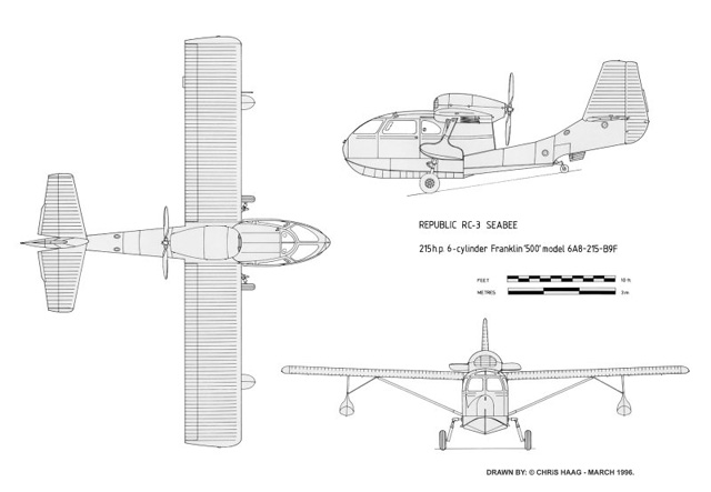
Republic RC-3 Seabee
3-view
Drawn by: © Chris Haag
|
|
GENERAL
|
|
|
Manufacturer |
Republic Aviation Corporation |
|
Address |
Farmingdale, Long Island, New
York, USA |
|
Model |
RC-3 Seabee |
|
Seats |
4 |
|
Approved Type Certificate No. |
A-769-1 |
|
Issue Date |
July 1, 1946 |
|
Tentative Issue Date |
September 16, 1946 |
|
Fuel Capacity |
75 US gal |
|
|
|
|
DIMENSIONS
|
|
|
Length
(Max) |
27 ft 10.75 in |
|
Height (Max Land) |
10 ft 1 in |
|
Cabin Width (interior) |
5 ft 4 in |
|
Cabin Height (interior) |
3 ft 10 in |
|
Cabin Length (interior) |
8
ft 10 in |
|
Baggage Compartment (volume) |
20 cu ft |
|
Draft Loaded |
1 ft 6 in |
|
|
|
|
LANDING GEAR
|
|
|
Main Gear |
Electrol Model 400-2 |
|
Tread |
96 in |
|
Base |
12 ft 10 in |
|
Landing Gear Travel |
7.5 in |
|
Main Wheels |
7.00-8 (4 ply) |
|
Inflate to |
30 psi |
|
Brakes |
Goodrich Model 6056A |
|
Tail Wheel |
Goodyear Model PD-173 (6 ply) |
|
Inflate to |
45 psi |
|
|
|
|
WINGS
|
|
|
Airfoil Section |
NACA
Clark Y |
|
Span |
37 ft 8 in |
|
Chord |
63 in |
|
Aspect Ratio |
7.23 |
|
Incidence |
3.5 deg |
|
Dehedral |
2 deg |
|
Total Area |
196 sq ft |
|
Aileron Total Area |
13.7 sq ft |
|
Flap Total Area |
25.3 sq ft |
|
|
|
|
EMPENNAGE
|
|
|
Stabilizer Setting |
-4.5 deg |
|
Stabilizer Total Area |
21.4 sq ft |
|
Elevator Total Area |
17.9 sq ft |
|
Fin Area |
22.8 sq ft |
|
Rudder Area |
10.5 sq ft |
|
|
|
|
WEIGHTS
|
|
|
Gross - Normal Class |
3150
lbs |
|
Gross - Utility Class |
2810 lbs |
| |
Empty |
2190 lbs |
| |
Power Loading |
14.65 lbs/hp |
|
Wing Loading |
16.1 lbs/sq ft |
|
|
|
|
SURFACE MOVEMENTS
|
|
|
Rudder |
±
30 ° |
|
Ailerons |
± 20
° |
|
Elevators |
±
28 ° |
|
Elevator Tabs |
± 25
° |
|
Water Rudder |
± 30
° |
|
Flaps |
Down
30 ° |
|
|
|
|
ENGINE
|
|
|
Manufacturer |
Aircooled Motors, Inc. |
|
Address |
Syracuse 8, New York, USA |
|
Models |
6A8-215-B8F
and 6A8-215-B9F |
|
Approved Type Certificate No. |
242 |
|
Number of Cylinders |
6 |
|
Rated Power |
215 hp |
|
Rated Speed |
2500 rpm |
|
Idle Speed |
500 - 600 rpm |
|
Reverse Propeller Speed |
(Max)
1750 rpm |
|
Crankshaft Rotation |
Clockwise |
|
Propeller Shaft Rotation |
Clockwise |
|
Propeller to Crankshaft Ratio |
1:1 |
|
Propeller Shaft Spline Size |
SAE 20 |
|
Cylinder Head Temperature |
Max. 525 ° F |
|
Fuel Grade |
80 Octane Nonleaded Aviation |
|
Fuel Consumption (Cruise) |
13.5
US gal/hr |
|
Fuel Pressure |
2 to 9 psi |
|
Compression Ratio |
7:1 |
|
Piston Displacement |
500 cu in |
|
Bore |
5 cu in |
|
Stroke |
4.25
cu in |
|
Fuel Pump |
Dual AC Diaphragm Type |
|
Carburetor |
Marvel-Schebler MA4-5 # 10-3007 |
|
Ignition (-B8F) |
Dual Eisemann Magneto Model LA-6 |
|
Ignition (-B9F) |
1 Scintilla Magneto + 1 Auto-Lite
Distr. |
|
Magneto Breaker Point Gap |
(Eisemann)
.019" to .021" |
|
Distributor Point Gap |
(Auto-Lite)
.020" |
|
Maximum Drop on Magneto or Distributor |
100 RPM |
|
Ignition Timing |
32 deg Adv. Left and Right |
|
Firing Order |
1-4-5-2-3-6 |
|
Spark Plugs |
Auto Lite AH4 |
|
Spark Plug Gap |
.014" to .018" |
|
Valve Clearance |
(lifter
bled down, cold) .040" |
|
Starter |
12 Volt, Delco |
|
Generator (Max 35 Ampere) |
E.AL. GGS-4801A-EO-8686 |
|
Oil Capacity |
13 qts |
|
Oil Temp (Max) |
260 ° F |
|
Oil Pressure (Max) |
50 psi |
|
Oil Pressure (Idle Min) |
20 psi |
|
Oil Capacity (thru s/n 24065) |
11 qts |
|
Oil Capacity (s/n 24066 and on) |
12 qts |
|
Oil Specifications (Above 40 F) |
SAE 40 |
|
Oil Specifications (Below 20 F) |
SAE 20 |
|
Max Time Between Oil Changes |
25 hrs |
|
|
|
|
PROPELLER
|
|
|
Model (Standard) |
Koppers Aeromaster |
|
Blades |
2 x maple-wood
laminate |
|
Diameter |
84 in |
|
Model (Reversible Option) |
Hartzell HC12x20-2 |
|
Blades |
2
x L8427 composite |
|
Diameter |
84 in |
|
Pitch |
+18 deg to -12 deg (reverse) |
|
|
|
|
PERFORMANCE
|
|
|
Max Structural Cruise Speed (Vno) |
117 mph TIAS |
|
Max Maneuvering Speed (Va) |
133 mph TIAS |
|
Never Exceed Speed (Vne) |
148 mph TIAS |
|
Max Flaps Extended Speed (Vfe) |
105 mph TIAS |
|
Max Gear Extended Speed (Vle) |
? |
|
Cruise Speed (Vc) @ 75% pwr |
103 mph |
|
Best Range Speed (Vbr) |
? |
|
Best Endurance Speed (Vbe) |
? |
|
Approach Speed (Vref) |
80 mph IAS |
|
Best Power-Off Glide Speed (Vbg) |
? |
|
Minimum Descent Speed (Vmd) |
? |
|
Stalling Speed (Vs0) -
Gear/Flaps Down |
58 mph IAS |
|
Stalling Speed (Vs1) - Gear/Flaps Up |
66
mph IAS |
|
Best Climb Angle Speed (Vx) |
? |
|
Best Rate of Climb Speed (Vy) |
75 mph IAS |
|
Rate of Climb (Sea Level) |
700
ft/min |
|
Service Ceiling |
12 000 ft |
|
Range at Cruising (71 US gal) |
520 miles |
|
Take-off Distance - Land |
800 ft |
|
Take-off Distance - Water |
1000 ft |
|
Take-off Time - Water |
25 secs |
|
Landing Run - Land |
400 ft |
|
Landing Run - Water |
700 ft |
|
|
|
|
Home | RC-1 |
RC-3
|
|
Updated: 2009-06-12
|

|
Copyright © 2006-2009 Steinar Saevdal
|
|